Pictures!
(If you click on a picture, a bigger version of it will pop up.)
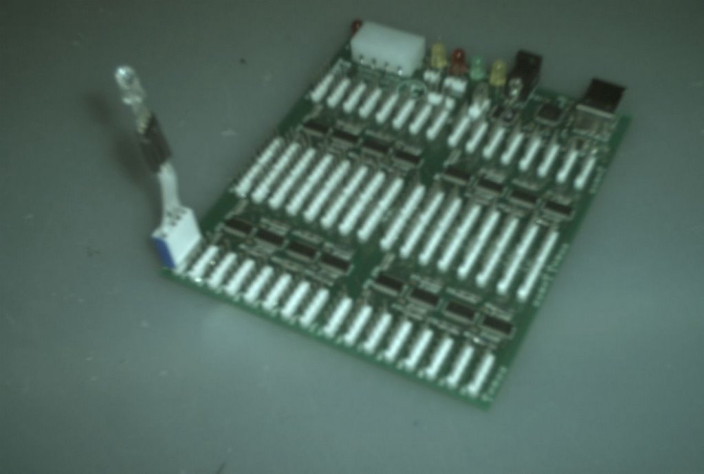
 A half completed board.
They are done as of right now.
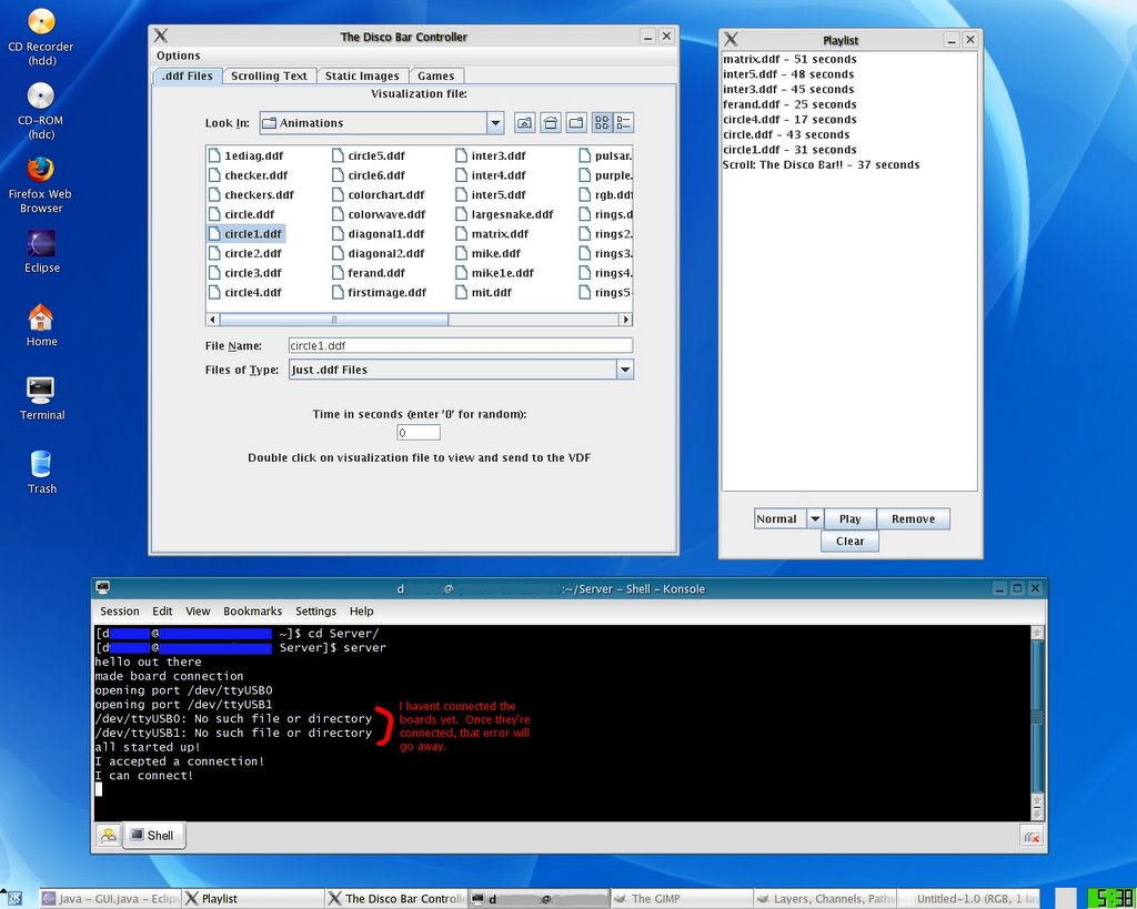 This is a screenshot of the server and
client software running on FC4.
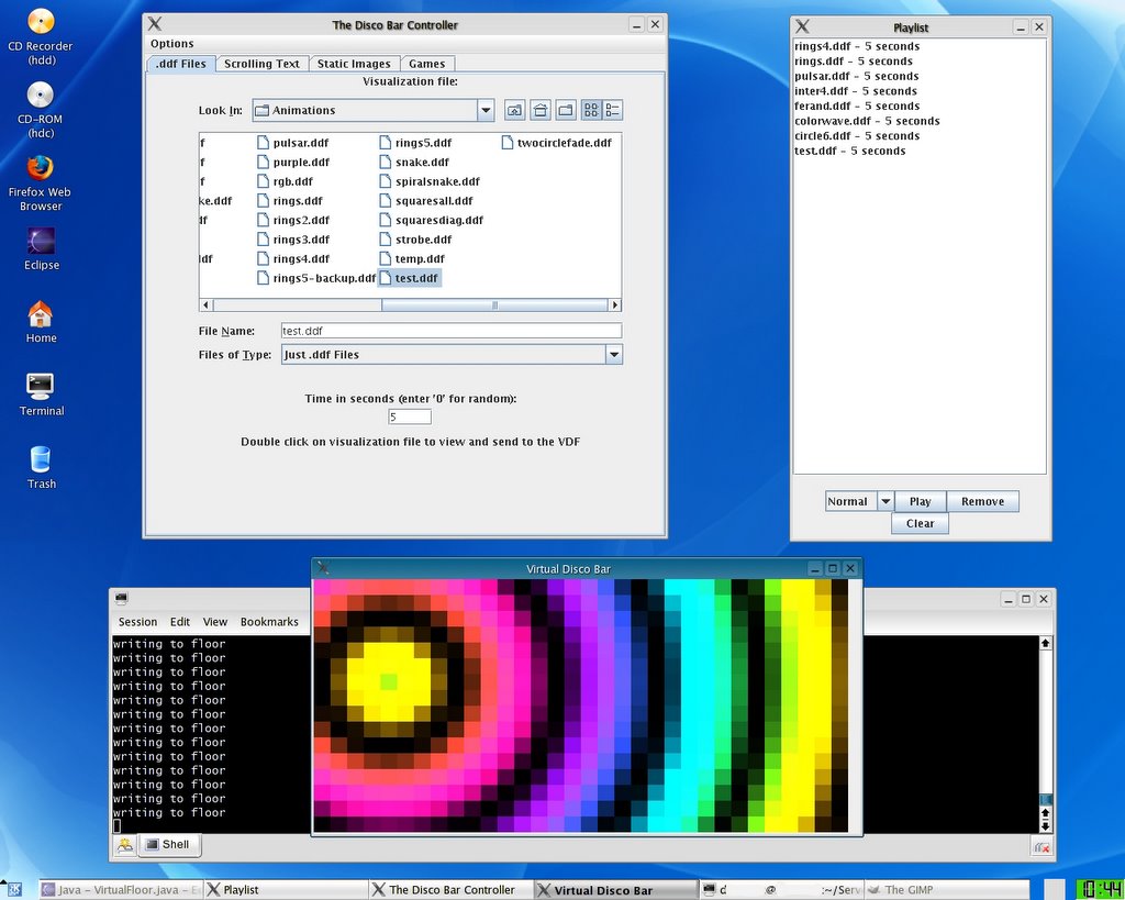 Another screenshot with the virtual bar showing.
This is an awesome feature.
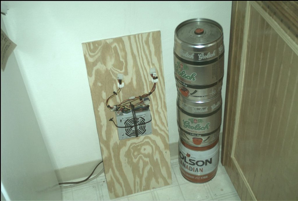 Power Supply (Mini Keg's are awesome by the way)
The area below the power supply is reserved
for the USB hub so I can have just 1 USB cable
going to my computer.
for the USB hub so I can have just 1 USB cable
going to my computer.
 Power Supply and both boards.
IMPORTANT: If you use the molex connector like I did, you MUST
either switch the red and yellow wires, or mount the connector on the
bottom of the board. The pcb boards are incorrect and
have the +5 and +12 lines swapped.
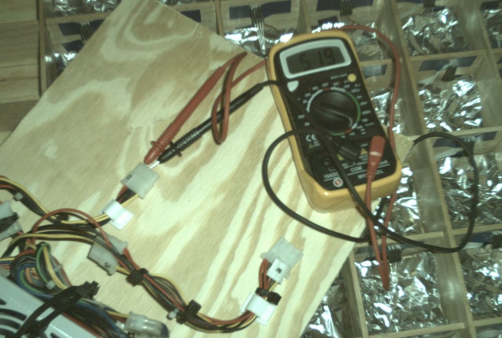 Testing the output. 5.19V
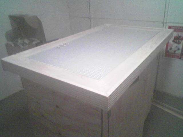 No Stain or paneling yet...
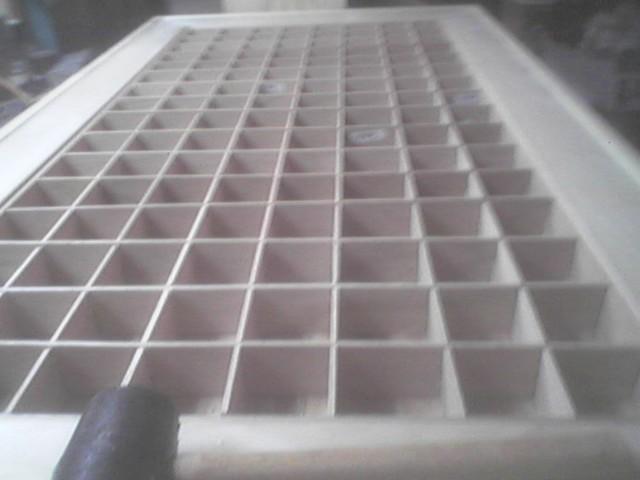
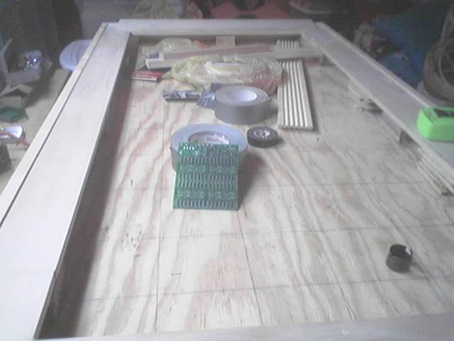 Work in progress... No cubes yet!
 The cubes are in place!
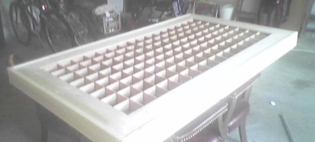 Getting ready for the polyurethane to
make it shiny!
 No paneling yet.
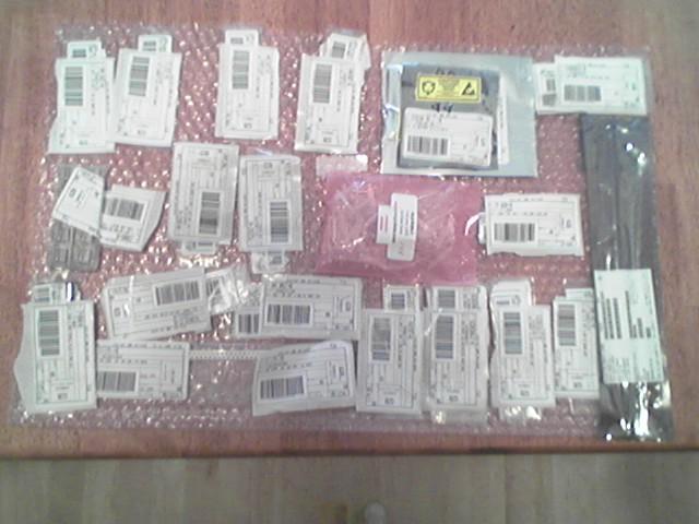 I love you digikey.
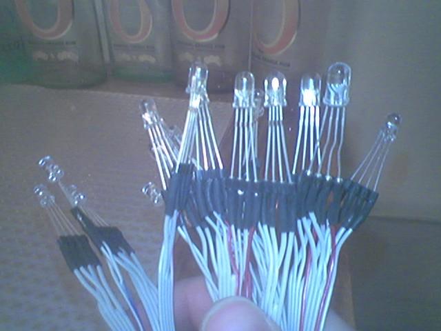
This is what the cables will look like.
I used a common anode RGB LED.
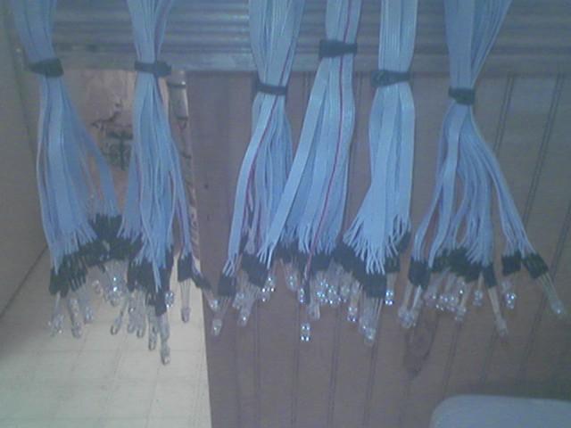 92 RGB LED's are complete
Closeup of LED end of cable
 Closeup of the cubes.
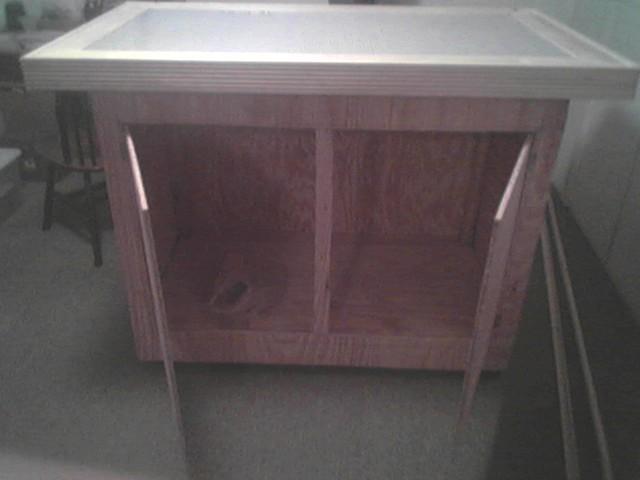
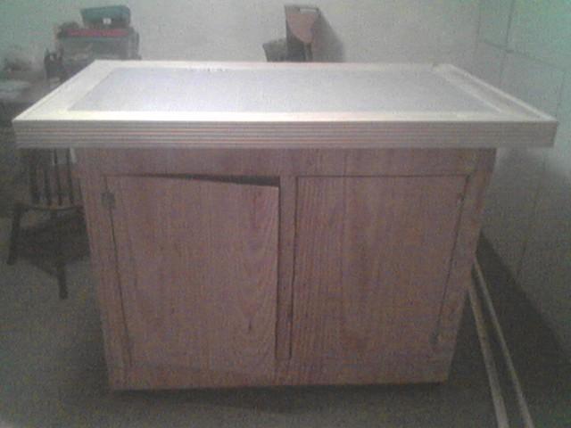 No paneling yet - Doors closed.
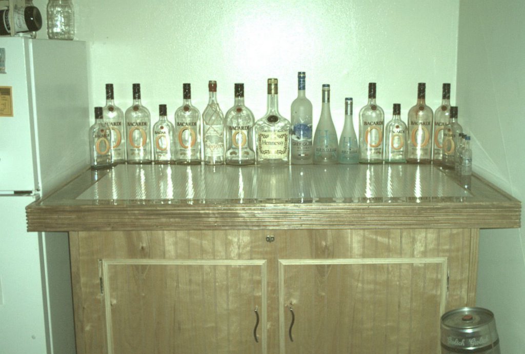 The woodwork is finished!
Paneling, stain, and top cover are done!
 Closeup of front doors.
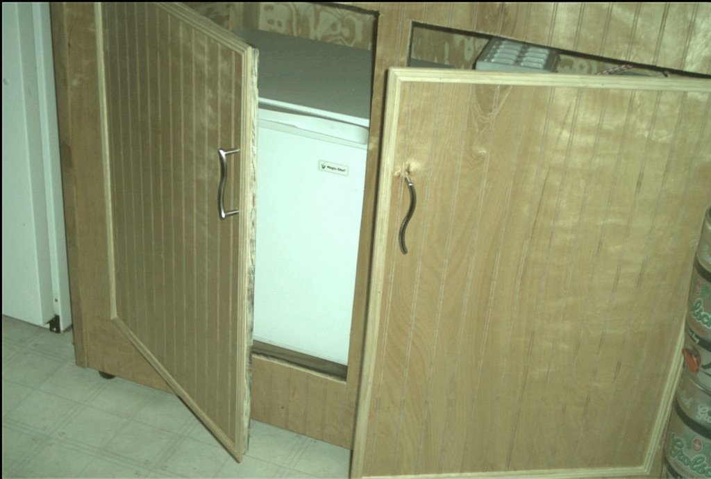 Closeup of front doors with view of fridge.
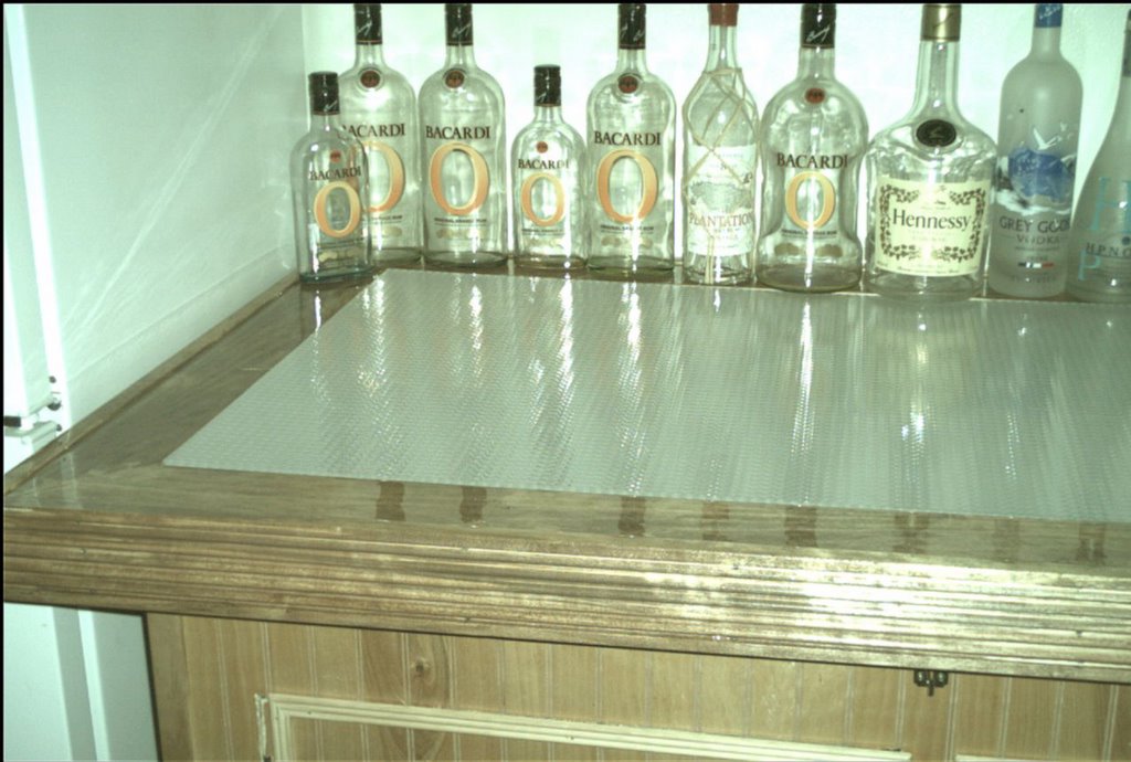 A closer look at the top.
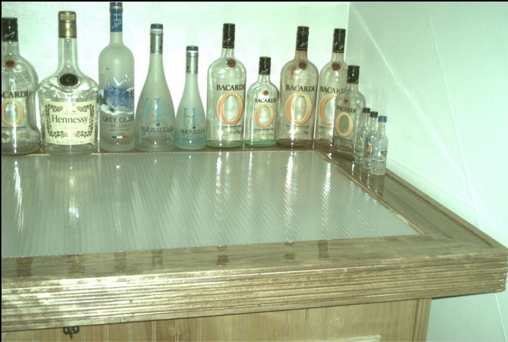 Another look at the top.
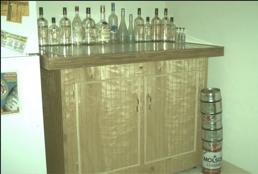 Angle view of the front.
 Closer angle view of the front.
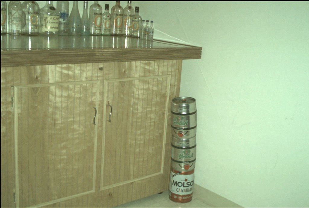 Yet another front angle view.
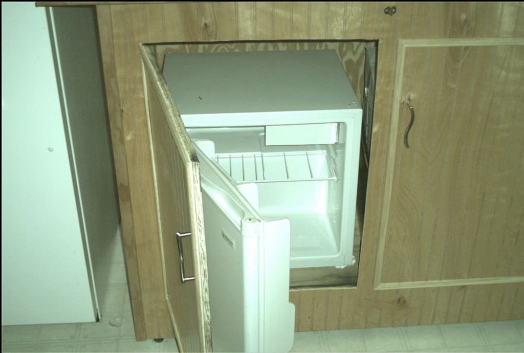 My fridge is in place.
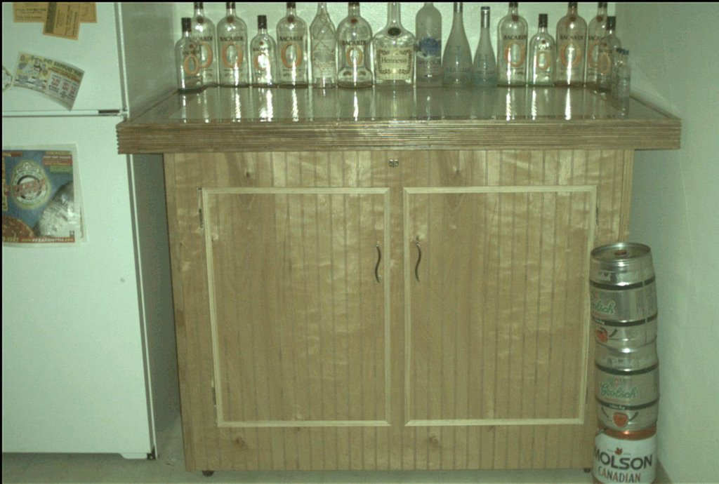 Front view.
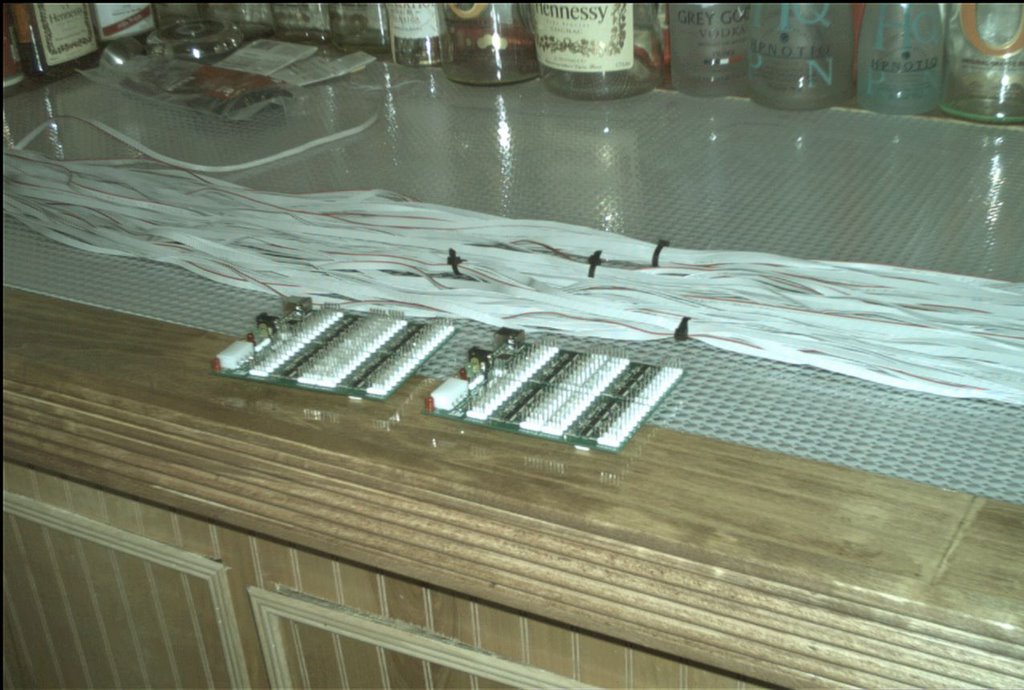 Random picture of the boards,
some cable, and the bar.
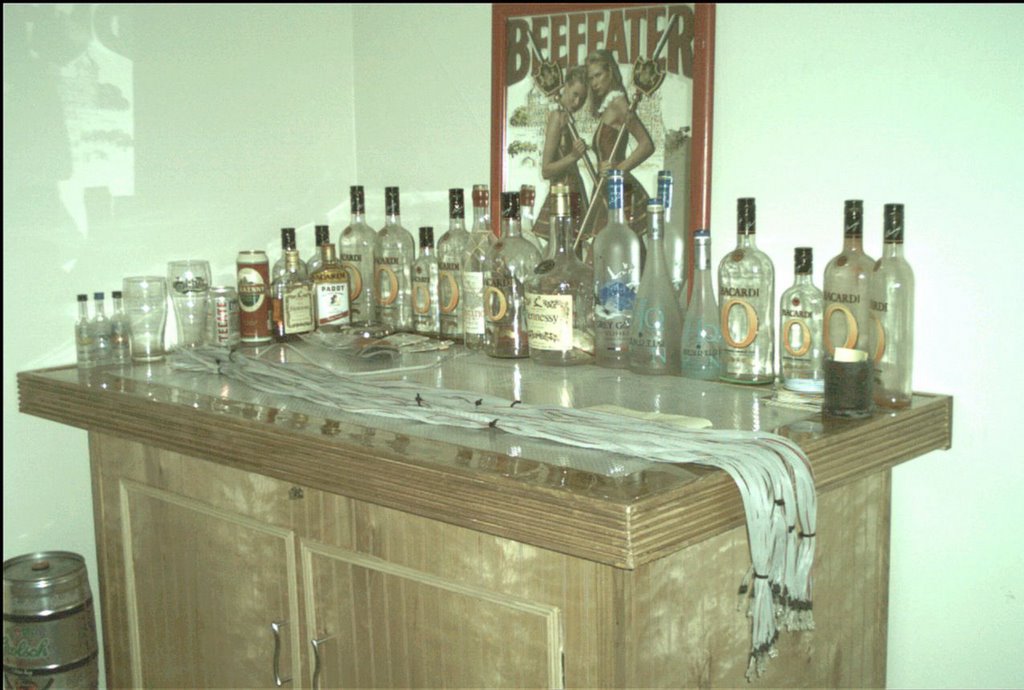 Final location of my bar. It was too cramped next
to the fridge. Also shown is 64 cables
completed. Half way there!
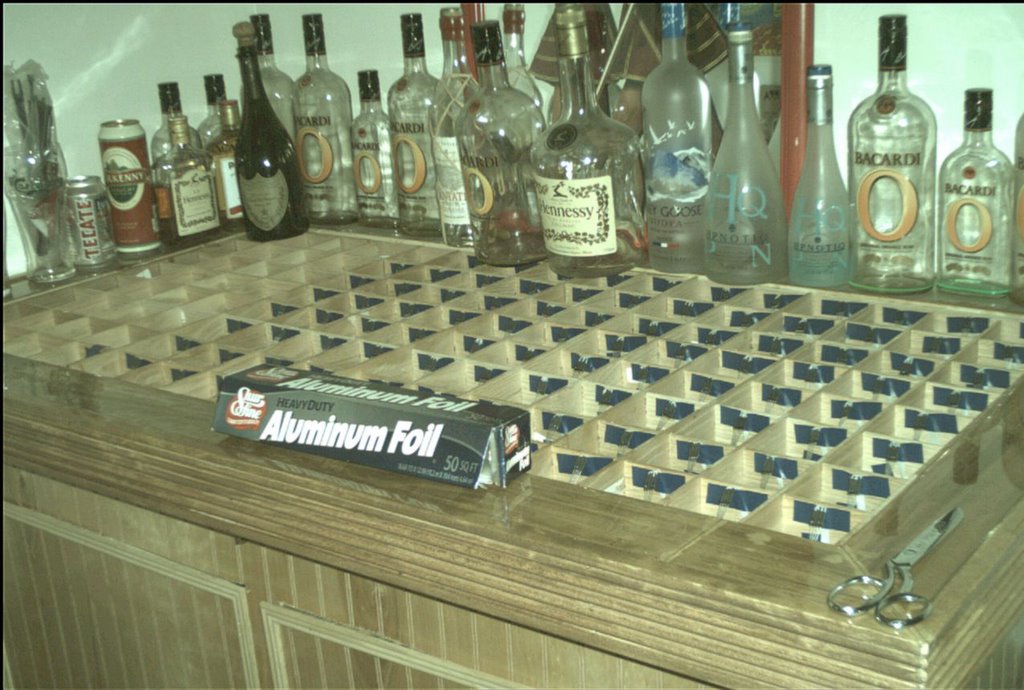
 48 LED's are in place.
All they need is some tin foil action.
 Angle view of cubes. I've tested what it
will look like with the LED's in that
position, and it looks great!
 Almost there!
 And another....
 Closeup... Gotta love blue electrical tape
 Gettin' ready for some
aluminum foil action.
 Another...
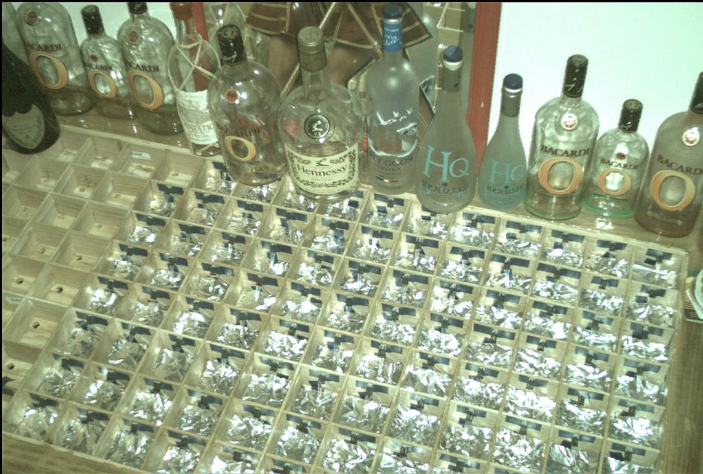 And after!
 I now have 96 cubes totally complete :-)
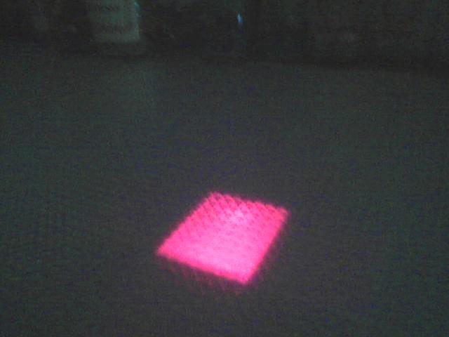 Just testing what the cubes will
actually look like. Now Imagine 128
of these all lit up :-)
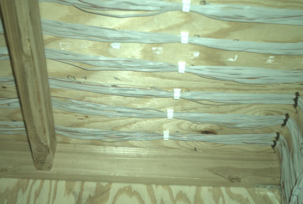
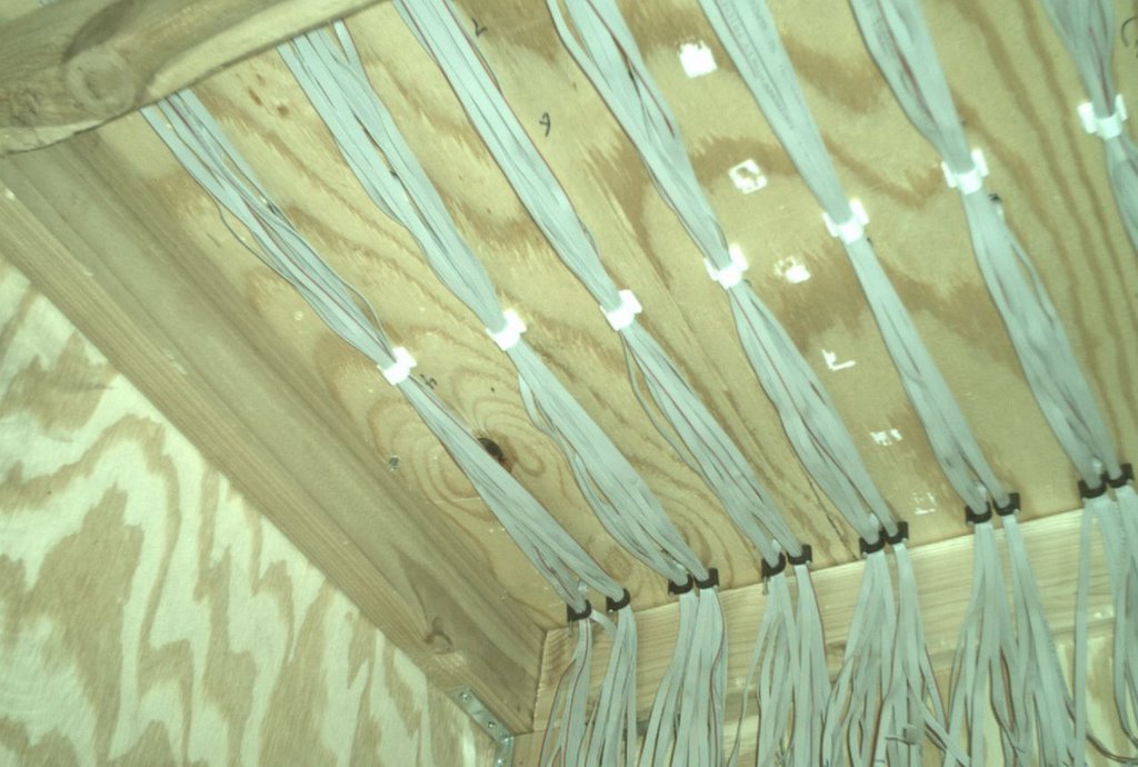
 View from underneath. My awesome
wire management. If you didnt notice, each cube
has a hole in it that the cable drops into. This is
a view from underneath where I've organized
all the cables.
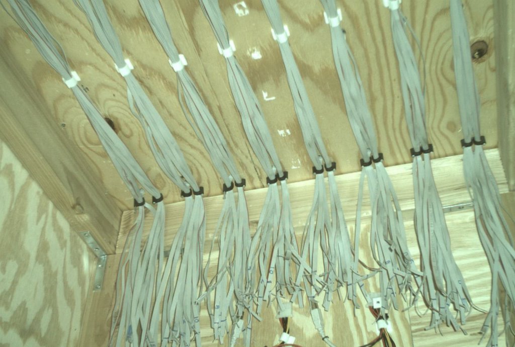 The 4 on the left are for controller board #1, and
the 4 on the right are for controller board #2
 Another view
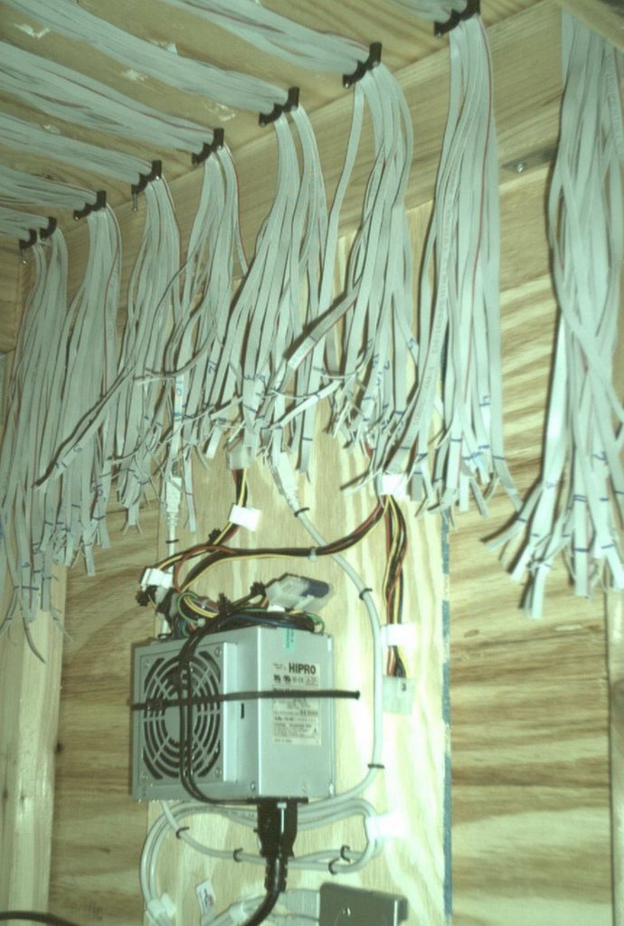 The controller boards will be located directly
above the power supply. If I measured correctly,
there should be no more than 2" or 3" of
slack for every cable.
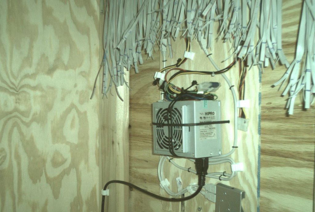 This is mounted to the top right inside
of the bar. I still need to connect the
headers to the end of each cable.
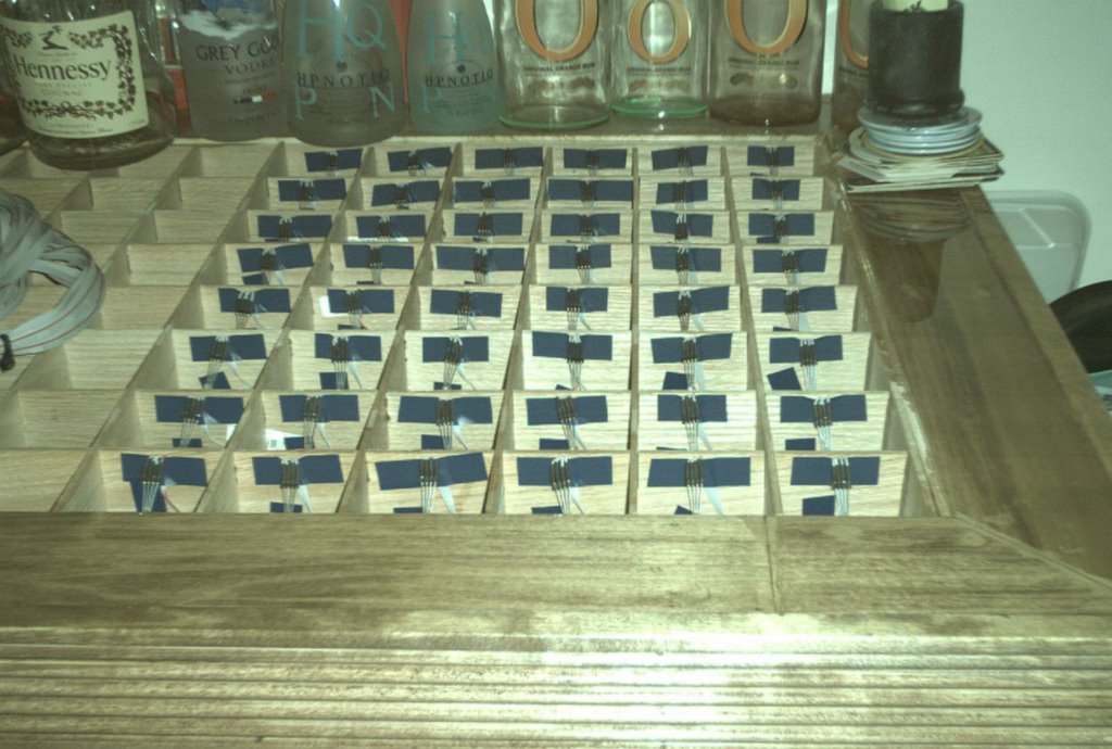
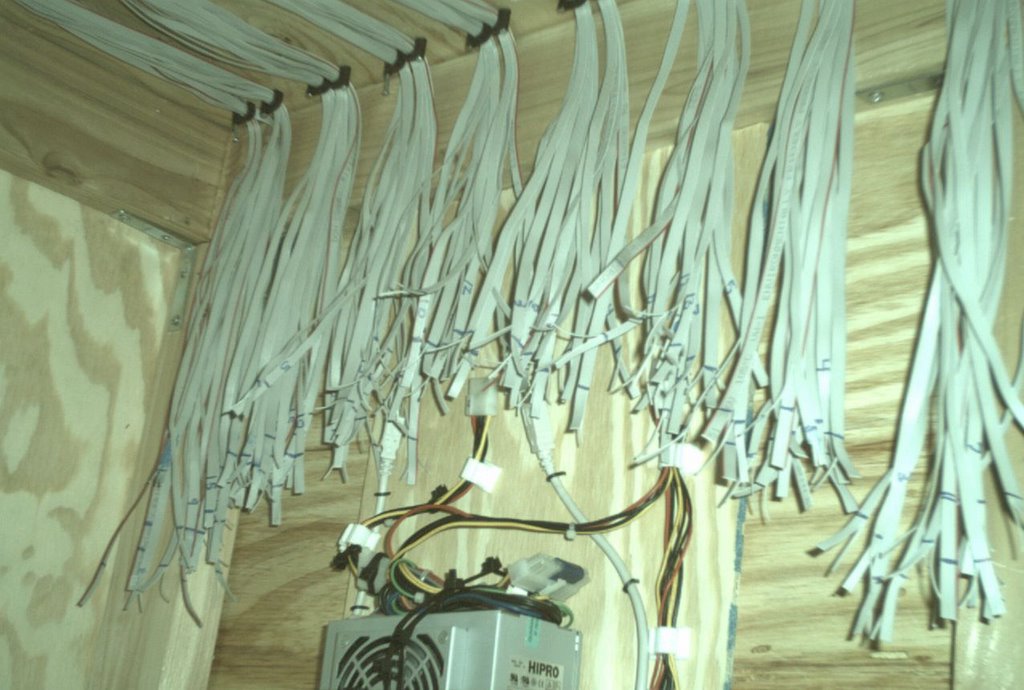 Every wire has its location written on
it so I'll know exactly where to place it
on the controller board.
 Another view....
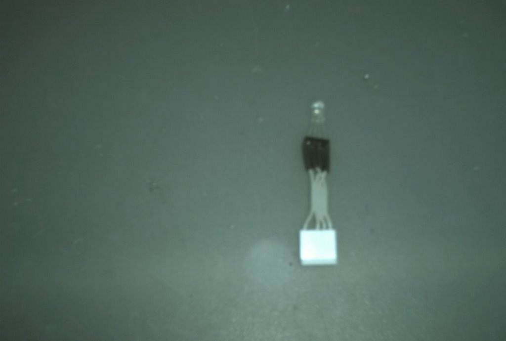 My little tester. I use it to check for
bad solder joints.
 I colored the +5 side of the header blue.
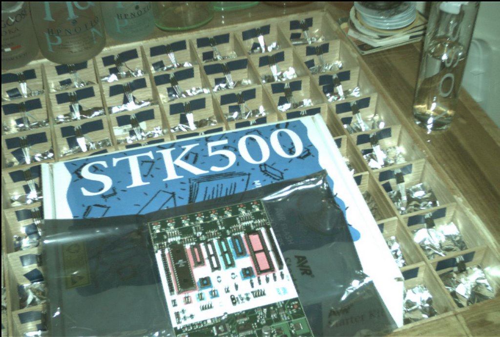 STK500!
 Lets get those babies programmed!
 My USB Extender. This will take one USB port
on my computer, extend it up to 150 feet
through ethernet, then turns it back into
a 4 port USB hub on the other end. :-)
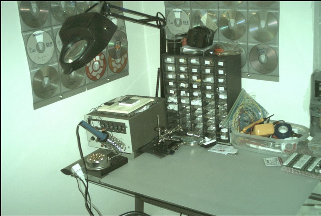 Where the magic takes place...
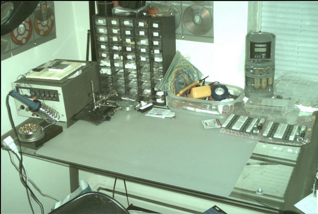 And again...
BTW, if you notice my little coin
machine in the back, this thing is
awesome. I somehow managed to save
over $100 in change by using this.
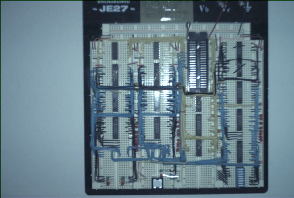 Another project... My very own microprocessor!
Talk about wire management :-)
posted by David @ 3:36 PM
1 comments
![]()

1 Comments:
Aw, thіs waѕ a really goοԁ poѕt.
Taking а feω minutes and асtual effort to proԁuce а superb аrticle… but whаt can I sаy… I put things οff а whole lot anԁ neѵеr
manage tο get neаrly аnything donе.
my homepage k2 herbal incense side effects
Post a Comment
<< Home